
1. Place the AF Meter on the
steering column (or wherever you want it)
2. Route the wires down the steering column and under the gauges
3. Continue to route the wires towards the gas pedal
4.
a. Remove the driver and passenger side foot panel of the center console to expose the ECU
b. Unbolt the ECU and pull it out to expose the wiring bundle
a. Remove the driver’s side center foot panel to expose the ECU
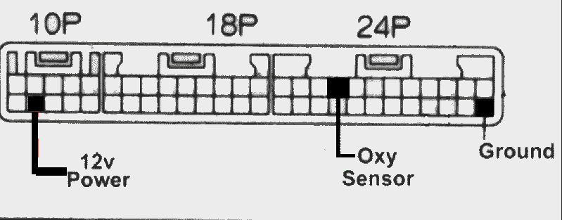
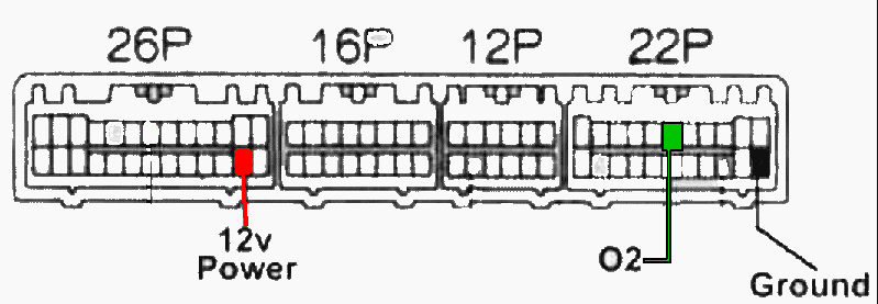
5. Using the picture below find the appropriate wires for a 1g or 2g DSM
1g

2g

6. Using the supplied taps, tap the AF Meter’s colored wires to
the colors shown in the diagram (actual ECU wire colors will not
match). Be sure you are referencing the ECU plug to the picture
correctly. It is not uncommon for people to have the ECU plug
upside down and connect the wires wrong
7. Tuck all excess wire so that it can not be caught by your feet and can not come loose due to vibration while driving
8. Replace the kick panel
9. Use the supplied Velcro to secure the AF Meter to the steering
column
10. Turn the ignition to ON. You should see the AF Meter power up.
(NOTE: the back light will not be visible in sunlight but will be
bright enough for night time viewing). If the unit does
not power up check the red and black wires for proper
connection.
11. Start the car
12. If the voltage does not start to cycle up and down after 2
minutes shut the car off and check the connection of the green
wire. That includes both that it is actually making a
connection AND that it is connected to the correct wire. This
has to be the #1 most common cause of emails to me with meter
problems. If the meter still seems to display a single value go
for a drive. If it cycles while cruising you then have an idle
mixture problem. If the meter still doesn't do anything it is
very likely that you have a dead o2 sensor. If the meter
displays battery voltage fine when the switch is toggled then the
meter is working correctly and it is either a bad connection or other
problem with your fuel control system.
13. Enjoy your new Backlit Digital Air Fuel Ratio Meter.
Notes about the AF Meter's operation:
- The AF Meter will initially show a very low value till the O2 Sensor warms up. At that point it should start to cycle high and low. If not check the connections and consider that your o2 sensor may very well be bad. It is more common that you think.
- Due to the 3 sample/sec refresh rate the AF Meter will appear to jump around a lot while in closed loop mode. This is not a problem when at WOT as the O2 value will not be jumping around as quickly.
- The AF Meter is NOT a diagnostic tool for testing the reaction time of the O2 sensor. It is meant as a monitoring device only.
- Negative values during high vacuum situations (coasting in gear) are normal and nothing to be concerned about.
- If you see 13.8 volts showing on the meter this is your battery voltage. Flip the switch on the back to see O2 voltage.
Every car is different when it comes to your tuning settings. This is because the air flow meters differ by up to 15%, (that is the reason for the adjusting screw). Any recommended settings are a starting point only. You set it by looking at the O2 voltage. The O2 sensors were never designed to be accurate to with in .1v For the most part these numbers will help but you can not compare numbers as gospel with someone else's.
At idle and part throttle you want to see the voltage cycling up and down between .2 and .8 roughly.
Typically it will go (O2 voltage):
.2-.8-.3.-.8-.1-.6-.2-.8-.3-.8-.4.-.9..2-.8-.2-.8.1-.9.........up and down, up and down, up and down........
When you go past 40% throttle the voltage will be set at what ever you have the AFC set at. This is the same for full throttle.
On 91 octane gas you will
want .94-.95v If you are at a higher altitude then lower
voltage is OK.
On 92 octane gas you will want .94v
On 93-94 octane gas you can get away with .92v
When the O2 sensor heats up after several runs, the voltage out put will drop off a little. What was .94v will drop to .92v. This is normal.
The O2 voltage will vary a lot more from car to car. Your numbers can vary from these easily by as much as .05v. 1G cars have more grounding issues and 90s in particular will read leaner (lower voltage) With a 1G car the compression is lower too so you can run leaner before getting knock that retards timing.
On 91 octane gas you will
want .89 to .91v If you are at a higher altitude then lower
voltage is OK.
On 92 octane gas you will want .88v
On 93-94 octane gas you can get away with .86v
The same applies to the O2 Voltage when the O2 sensor heats up, it will drop some.
For more info see http://www.roadraceengineering.com/newafc.htm