
SCC Magazine Project Eclipse – More boost!
Sport Compact Car Magazine, October 1998
by Keith Buglewicz
PHOTOGRAPHY: LES BIDRAWN, KEITH BUGLEVVICZ
We Continue or Quest for Elusive Extra Boost
Our Project Eclipse has come a long way since we first got the car back in May of last year. Our first upgrade was to the suspension and throttle response. The suspension improvements-four Eibach springs and four Koni adjustable struts-worked like a charm, calming the sometimes-wallowy ride of the Eclipse. To fill in the vast, vacant wheel wells, we added 18-inch Kosei Seneca wheels and Dunlop SP9000 tires. The engine upgrades consisted of a cat back exhaust, an intake and a better intercooler pipe, and worked surprisingly well to give the Eclipse a measured gain of 32 hp. Next, we added an Apex electronic boost controller and AFC fuel computer in a quest for more boost. They helped, but we were limited by, the inefficiencies in the stock turbo. We took care of that with a new turbo that had been thoroughly massaged by Turbonetics. The improvement was drastic.
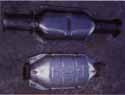
The differences in the stock catalyst and Random Technology catalyst supplied by HRC are dramatic. The overall shape is the same; however, the inlet and outlet pipes on the Random catalyst are monstrous compared to the Stock unit
But there was still more work to do. With the bigger turbo, the stock fuel injectors were at maximum capacity, often running at over 90 Percent duty cycle at higher revs (the Apex AVC-R boost controller can read injector pulse width). It was clear that if we wanted to run more boost, we needed more fuel. in addition, we wanted to complete our exhaust system modifications with a three-inch downpipe and catalyst from Hahn Racecraft (HRC).
The cliché says a chain is only a strong as its weakest link, and that was the case in our Eclipse’s exhaust system. The stock turbo outlet had been ported by Road/Race Engineering when the new turbo was installed (see “Project Eclipse”, March 1998). We wanted to find out how much of a difference installing a full three-inch exhaust system would make on the car, however. There were few problems on the intake side, with a free-flowing air filter, blockage-free intake pipe and a round (instead of kinked and flattened) intercooler-to-throttle body pipe. However, the engine couldn’t quite get the exhaust out properly because of the puny catalyst inlet and outlet, and the small pre-cat half of the exhaust system.
HRC offers an excellent selection of Eclipse performance parts, and their new 3-inch downpipe caught our eye; a beautifully crafted stainless steel piece with nice straight welds, a built-in flex joint and all fittings and fasteners needed to get the job done. The catalytic converter was from Random Technology and features a 3-inch inlet and outlet. This contrasted with the stock cat, which actually necked down a little from the stock 2.25-inch pipe, causing a major flow restriction. The idea behind the HRC system was it should be used to modify an existing 3-inch cat-back system. In other words, you have to cut off part of the existing performance exhaust system on your Eclipse and weld on a new flange to use the HRC system; something of an advanced procedure. Most cat-back exhaust systems for the Eclipse start out at 2.5-inches so this is the only way a 3inch downpipe and cat can be added. To do it properly, a good lift, saw and welding tools are needed. In other words, take it to a professional.
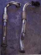
Note how the stock downpipe chokes down considerably after the cast iron collector. Keep in mind that the majority of the width shown by the stock system is heat shields the HRC piece is a true 3-in. pipe.
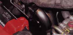
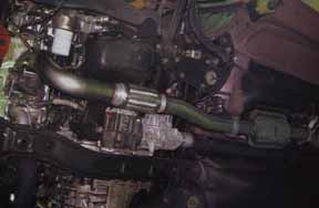
The easy part was getting the HRC pipe in part was reaching up into the tight confines of the engine compartment and bolting the pipe to the flange of the turbo.
You can see why getting the pipe on was so difficult. Note there are two more bolts not visible here, HRC even tapered one bolt (under the waste gate pipe) to make getting it in a little easier, Regardless, it was a tight squeeze. With the pipe in place, changing the oil filter is also a little more difficult, but the pipe was carefully designed to give exactly enough room to get the filter out.
Attaching the new catalyst to the existing exhaust system was supposed to he straight The flange from the old system would he cut off, the new flange welded on, and the whole shebang would just belt right together It didn’t quite happen that way
Once again, we utilized the talents of the technicians at Road/Race Engineering in Huntington Beach, Calif., for the installation. Installation of the new pipe appeared to be straightforward … at first. The three-inch downpipe was a tight fit, and only after some serious grunting, groaning and a series of words unprintable here did we finally get the pipe in place. The fault didn’t lie with the downpipe itself; there just isn’t a lot of room to work in the Eclipse’s engine compartment. Installation necessitated removing all the heat shielding from around the turbo, and removing the radiator fan as well for extra clearance. The stock downpipe was extracted as one piece from the car, and was relatively simple to remove. The HRC piece, on the other hand, proved difficult. The stock cast iron collector South of the turbine is physically much smaller than the HRC piece, and does not incorporate the long external waste gate runner the HRC pipe does. As a result, getting the HRC pipe to fit required a little extra effort. HRC is aware of the tightness of the compartment, but aside from supplying a special tapered bolt to clear one of the tightest spots and some hints on getting their pipe in, there is little they can do.
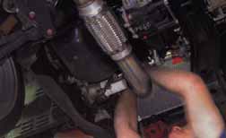
The second part of the system proved to be more challenging than the first. We had to cut off a considerable length of pipe to get to the three-inch portion. This caused a cascade of problems. Note the dogleg bend in front of the resonator; this had to be custom fabricated later.
Mike Welch from Road/Race utilized a three-inch resonator to replace the one cut off in our exhaust system surgery. He also fabricated the necessary dogleg bend from spare three-inch pipe. To keep the OBDII system happy-Mike cut the oxygen sensor mount off the old exhaust and welded it onto the new one. The new system looked considerably beef ier than before. Note that although there were some tight clearances, nothing rubs against the bodywork, and the car only scrapes on very high center bumps that would give most lowered cars trouble,
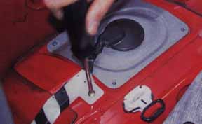
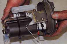
With the exhaust system in place, it-was time to replace the fuel pump and injectors. The pump was first. After the rear seat was removed, the access panel for the fuel pump was unscrewed and removed.
Attaching the new catalyst to the existing exhaust system was supposed to be straightforward. The flange from the old system would be cut off, the new flange welded on, and the whole shebang would just bolt right together. it didn’t quite happen that way. Everything seemed to be going smoothly until we realized the combined length of the HP( pipe and catalyst was too short. Once again this had little to do with the HRC ‘tern and more with the exhaust system we already had on the car The cat-back exhaust we used on the car didn’t flare out to its full 3-inch diameter until about 2 feet past the catalyst, which was where we made our cut. This extra length was too far for the HRC piece to span, eve with the long pipes on the ends of the Random Technology cat. So, we had to improvise. like any good tuner shop, Road/Race had lots of extra parts on hand. Among them was a sizable length of 3-inch steel tubing that was easily cannibalized for exhaust system duty. We also decided to add a 3-inch resonator to take the place of the one we had cut off the cat-back system (since the car is often driven long distances, a droning exhaust was the last thing we wanted). Mike Welch carefully measured the length needed and cut off the piece needed to make the system fit. Once again, we seemed to be on track until another problem reared its head.
Although the extra length of pipe and the new resonator were fine length-wise, they just weren’t lining up with the catalyst. The piece we had cut off incorporated a small dogleg bend. The bend compensated for difference of about a half inch in our modified system.
Since no amount of straining would bring the two together, Mike again came to the rescue by cleverly cutting the short length of pipe in front of the resonator. He was then able to line up the two pieces at last. Mike also cut a new hole for the stock post-cat oxygen sensor, keeping the OBDII system happy. Once the pieces were finally cut to fit, they were spot welded in place, and finally seam welded.
Despite the difficulties, the Frankenstein exhaust system looked terrific under the car. The extra welds and bends did nothing dynamically to restrict flow, and we now truly had a 3-inch “turbo-to-tip” exhaust system. The car now sports a deeper, richer exhaust note at idle that turns into a loud, angry blat at full throttle. We should point out that the exhaust does occasionally scrape, but only over high-centered clearances that would challenge almost any lowered vehicle.
The seat-of-the pants results were pretty good. Although the car didn’t need FAA certification, it certainly had better throttle response, along with better turbo spool up, which was mainly what we were looking for The differences in top-end power felt incremental at best, though, with no immediately noticeable difference at the high end of the tach. What was immediately apparent was that the system was flowing a lot more air.
How could we tell? A blast to redline on a cold day would cause the fuel cut to step in after the computer noticed the injectors hitting nearly 100 percent duty cycle. After a few of these incidents, the check engine light came on as well. Since this increased fuel and air flow didn’t seem to be accompanied by a substantial boost in high-end power, we theorized that the computer was over-fueling the car. To keep the engine safe from detonation, the computer was going dead rich, too rich to make any more power. The other hint that this could be the case was the blue faces of that followed the Eclipse in traffic raw gas smell was a little strong.
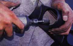
The official Mitsubishi tech manual prescribes a special tool to remove the large retaining collar that holds the fuel pump in place. Road/Race discovered another equally effective-if less elegant-way to do the same thing using much more common tools,
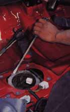
The electrical connection for the fuel pump was disconnected. In order to depressurize the fuel system, Road/Race turned on the car with the fuel pump disconnected. The car simply used up the fuel in the lines and died, They then disconnected the battery before proceeding. Even though the fuel system Was depressurized, there was still gasoline in the lines. If you are doing this procedure yourself, make sure You have something handy to catch the excess gasoline that spills out when the fuel lines are disconnected.
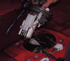
The fuel pump, float and sender all came out as one assembly. You may want to cover the open hole to the gas tank with something to prevent debris from falling in.
The replacement pump is physically much larger than the stock unit, and requires a lite modification of the various brackets to properly mount. Installation of the pump back into the tank is the reverse of removal.
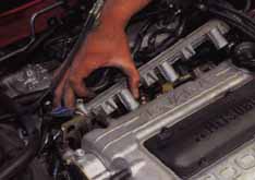
To replace the fuel injectors, all fuel lines to the fuel rail were disconnected, the injectors were unplugged and the rail was removed. If it can be removed with all four injectors attached, all the easier for the installer. Note the ‘A’shaped retainers above the plug for each injector. These need to be ground down to fit the new injectors.
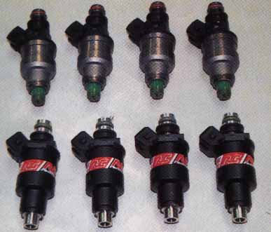
The RC’s injectors we chose flow 550 cc/min over the stock 450 cc/min (a 23 percent increase in capacity).
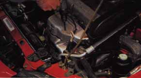
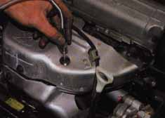
To monitor how much fuel we were giving the engine, we installed an exhaust gas temperature gauge from Apex The first step was drilling a hole for the temperature probe in the exhaust manifold. The hole should be as close as possible to the exhaust port without interfering with it. Mike actually drilled the hole in the manifold while the car was running, blowing any shavings back out the hole instead of allowing them to fall down into the turbo.
Carefully fiddling with the Apex AFC, we dialed the air flow meter input back four percent across the entire range (by simply turning each knob back four ticks). This dramatically improved power, throttle response, odor, and caused the check engine light to go back off. We were hesitant to tune any further, though, since we had no Exhaust Gas Temperature (EGT) gauge to see how our tuning was going (exhaust gas temperature is a good indicator of fuel mixture.)
Cold mornings still brought the injectors close to 100 percent, and we were eager to try more boost, so we made a call to RC Engineering in Torrance, California, for a set of new 550-cc injectors. RC Engineering is one of the best-known names in fuel injection technology. Its injectors are all flow matched so each injector in a set flows as close to the same as is possible. in an unusual twist, Russ Collins (the “RC” in “RC” Engineering) does not concentrate as much on fuel atomization as one would think. We all know what we think an injector spray should look like-a fine mist that sprays evenly from the tip of the injector. However, Russ showed us an injector equivalent to those provided for our Eclipse on his custom strobe-light-equipped spray observation station.
What we saw was surprising … no light mist, but a steady stream of fuel (well, test liquid, but you get the idea) that would shoot directly into the combustion chamber. Russ says that the atomization takes place in the turbulent environment of the combustion chamber, and that it isn’t necessary for the injector to do the job. The narrow stream is less likely to condense on the walls of the intake port, making the fuel mixture more consistent.
The probe simply screwed into position, with the lock nut keeping it in place.
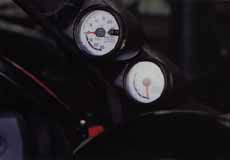
We mounted the EGT under the boost gauge in the Eclipse on the A-pillar. Road/Race supplied us with a double pillar mount to replace the single pillar mount. Like the first one, it had to be modified to fit the slightly oversized Apex gauges.

To give the piece a more stock appearance, Road/Race also painted it the factory gray of the rest of the interior.
The result was an ergonomic placement of the gauges right in line with the driver’s sight.
Installation of the fuel injectors was another reasonably straightforward procedure. Because it involved working with raw gasoline, it was a good idea to disconnect the battery to prevent any sparks. The entire fuel rail was removed, the new injectors were put in place, and the rail was popped on. Well, almost. Because the RC injectors have a slightly different connector location, the stock Mitsubishi rail had to be trimmed slightly. Simply a matter of grinding off some excess metal on the rail around the plug for each injector proved to be minor surgery.
With bigger injectors, the stock fuel pump would not be up to the job of providing adequate fuel pressure, so Road/Race also installed a larger Denso fuel pump.
The fuel pump was an in-tank unit, which meant removing the rear seat to get at the access hole on top of the tank. Once the pressure was relieved from the system and all hoses and connectors were removed, the large plastic ring holding the fuel pump in place was removed. The pump was removed as an assembly with the float for the fuel gauge. The pump itself was a metal cylinder about 4 in. long. The Denso replacement unit was substantially larger, and required a bit of modification to get onto the stock bracket.
With the larger injectors, the engine would automatically run way too rich, so we would have to use the AFC to dial in the fuel mixture. With this much fuel mixture fiddling, we absolutely needed an EGT gauge. So, we turned once again to Apex for an exhaust gas temperature gauge with a white face to match our boost gauge. Mike Welch of Road/Race showed us a good trick for installing the EGT probe in the exhaust manifold. To install the probe, you must drill and tap a hole in exhaust manifold. To prevent metal shavings from dropping into the manifold, and subsequently into the turbo, Mike drilled the hole while the engine was idling. This way, the exhaust blew the metal shavings out the hole and saved us a lot of worries.
As simple as this technique seems, Mike was quick to caution the inexperienced not to try it at home. it takes a great deal of finesse and practice to get the procedure down right one wrong move and a big piece of metal could fall into the turbo, with disastrous results. The safe way to do it is to remove the manifold altogether.
Once the hole for the sensor probe was drilled, it was relatively simple to route the lines to the gauge, which we mounted on the driver’s side A-pillar next to the boost gauge. mike tells us that the exhaust temperature should be 900 degrees Celsius at full throttle when everything is operating smoothly. Getting the temperature to that level involved tuning our gas flow with the Apex AFC fuel computer This procedure takes a while, and can be disastrous if done wrong. If in doubt leave it to professional tuners like those at Road/Race.
Initially we rough-tuned the car to run smoothly, and keep the exhaust conservatively cool. Tuned this way, the car made the same power it did before we did all this work. At the time we went to press, Road/Race was in the process of tuning it more precisely in the hopes of getting better power results. As we have observed before, the stock computer is getting very conservative about fuel and timing. Though you can tune this out somewhat with the AFC , you are only adjusting the air flow meter input to the computer, not adjusting the output. To really get things right, the ECU has to be re-programmed to remove the conservative fuel and timing maps. We plan to have this done, but in the mean time, we want to see exactly how well the engine can be tuned with the AFC. With the AFC tuned conservatively, the HRC downpipe and cat and the bigger injectors have only gained us responsiveness and status in the parts hanger’s club. The tuning step will be critical to making these mods worthwhile. The results of the tuning, however, will have to wait until the next installment.
